1) Disconnect battery and mount the CDI.
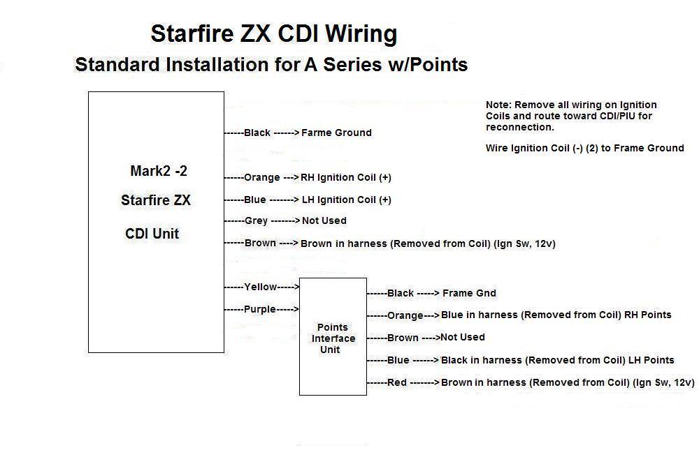
2) Identify the left and right ignition coil primary leads, these terminate in 4 bullet connectors. Disconnect the 2 BROWNs and the BLACK, BLUE from each coil.
3) Make up two short wires with suitable connectors and ground the NEGATIVE (-) terminal, one on each coil. (IGNITION COIL COMMON) securely to the frame.
4) Connect the ORANGE wire from the CDI to the active terminal (+) on the coil (ignition coil right)
5) Connect the BLUE wire from the CDI to the active terminal (+) on the coil (ignition coil left)
6) Connect the CDI BROWN wire to the BROWN removed in step 2
7) Mount the Points Interface Unit where it can easily be seen when adjusting the timing.
8) Connect the CDI YELLOW, PURPLE to the PIU YELLOW, and PURPLE.
9) Identify the 2 wires coming up from the point assemblies in the magneto, these are the BLACK and BLUE from step 2
10) Connect the PIU ORANGE to the BLUE in harness from step 2 (points left)
11) Connect the PIU BLUE to the BLACK wire
in harness from Step 2 (points right)
12) Connect the BLACK wire from the
CDI to a firm ground
13) connect the PIU RED wire to the connector BROWN from step 2
14) Connect the PIU BLACK wire to a firm ground.
The bike will now run.
Note: The GREY wire is used to disable the ZX MK2 unit. This wire is taken to ground through the kill, or engine stop switch. This wire can also be used with a hidden switch as an anti theft, or used with an external rev limiting RPM counter. Current through this wire is approx 12 milliamps. If not used, this wire can be cut and ignored. IMPORTANT: If the ignition key is left on with the kill switch enabled, the CDI will be in standby mode and still consuming battery power.