Starfire ZX Mark2
Ignition Kits
for vintage Kawasaki,
Yamaha, Suzuki, Honda
dayleedwards@rushpost.com
Taylorville, Westland, NZ
ZX Mark2 -2 Kit: Kawasaki Twins, Yamaha RD,
Suzuki Twins, Honda CB Fours - $128USD + $35
shipping
ZX Mark2 -3 Kit: Kawasaki Triples (exc H1),
Suzuki GT Triples - $128USD + $35 shipping
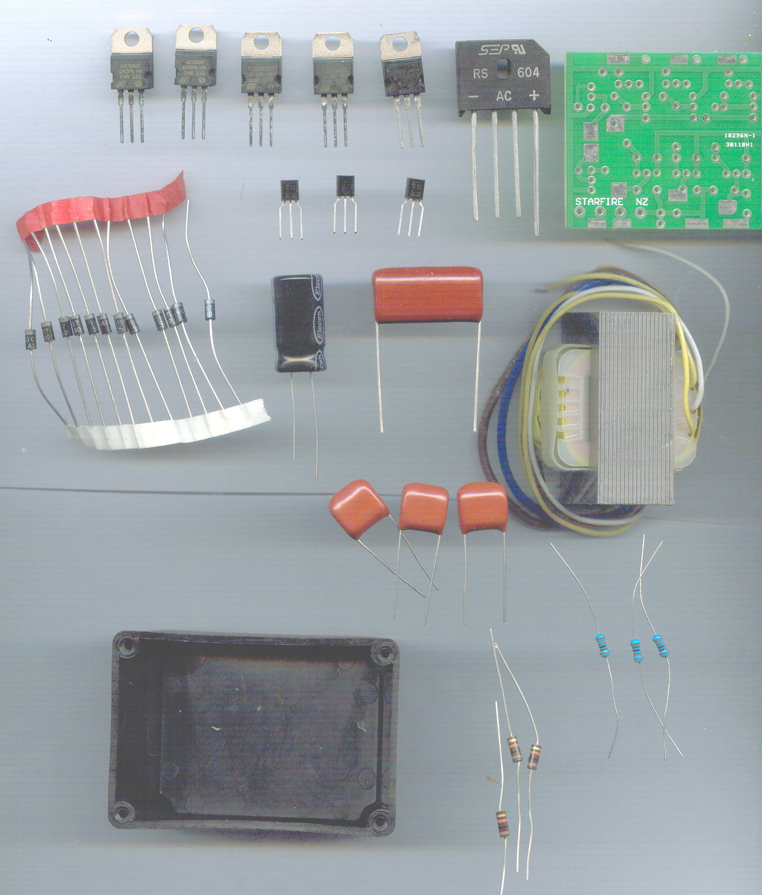
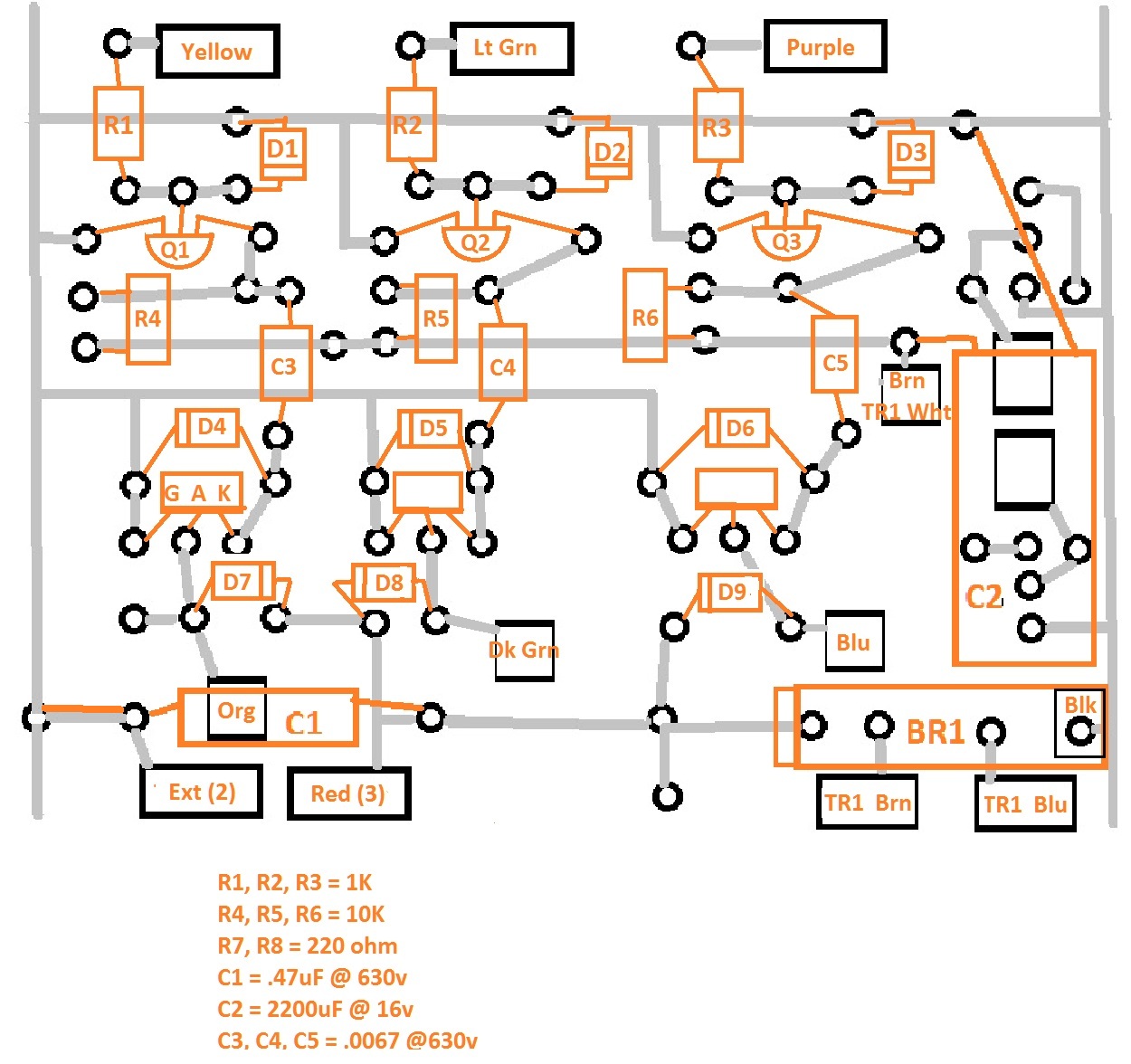
Circuit board assembly... PCB ... all units.
It is absolutely vital that all components are inserted correctly and in the right polarity. All directional components are marked. Diodes have a stripe, SCRs and Transistors are leaded left to right, electrolytic capacitors have a long and short lead, as do bridge rectifiers. Identify each component before inserting into the PCB, and double check before soldering to the pads. Just ONE mistake will prevent the unit working, and will likely damage other components.
1) Clean the board with meths to remove any residue.
2) Begin by inserting the smaller components... this usually makes it easier.
The diodes MUST go the correct orientation. The SCRs are inserted and "splayed"
a little from each other to prevent the tabs from being too close. The leads of
the BT149 must formed to fit the triangular board pattern. after each connection
is soldered, clip the excess lead close to the board, and resolder to be sure.
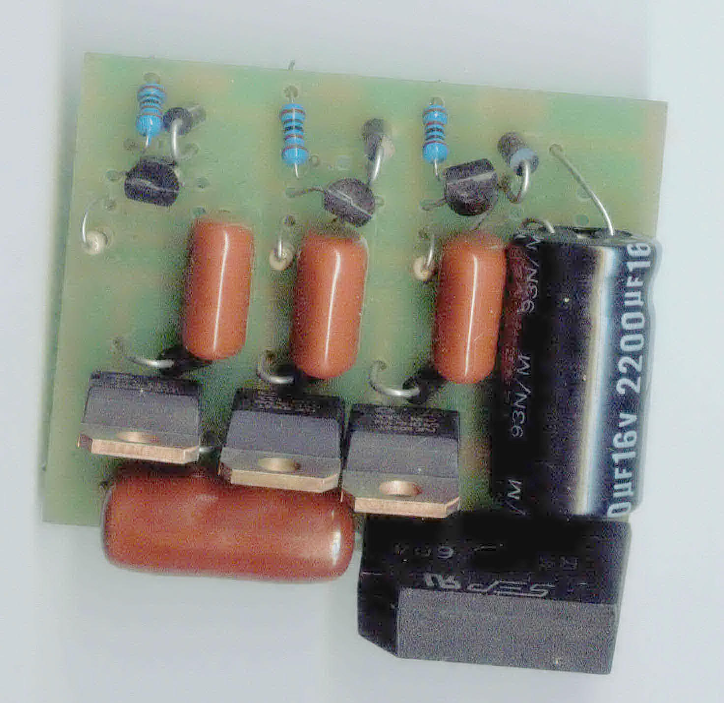
Some components mount on end. When fitting the larger components, press these
close to the board, there is very little room in the box once assembled.
NOTE: C1, the large ZX2/3 discharge capacitor MUST have the grounded lead
extended out to the ground PC track on the edge of the board. The lead is
clipped slightly long, bent over and soldered to the track after scraping back
the green resist coating to reveal the copper.
3) Double check the board matches the diagram overlay. Double check ALL connections are soldered. Double check there are no "solder bridges" between pads.
Notes when soldering.
Use a clean, tinned hot iron, NOT a soldering gun... these will destroy the PCB.
Heat the joint with the iron for around one second, and then touch the solder to the joint.
The solder should flow, and "wick" into the joint, and be shiny and smooth.... NOT blobby.
Use rosin cored solder, DO NOT use any acid flux... this is not a plumbing job.
If in doubt, practice first.
Click on image for full size view.
ZX Mark 2 -3
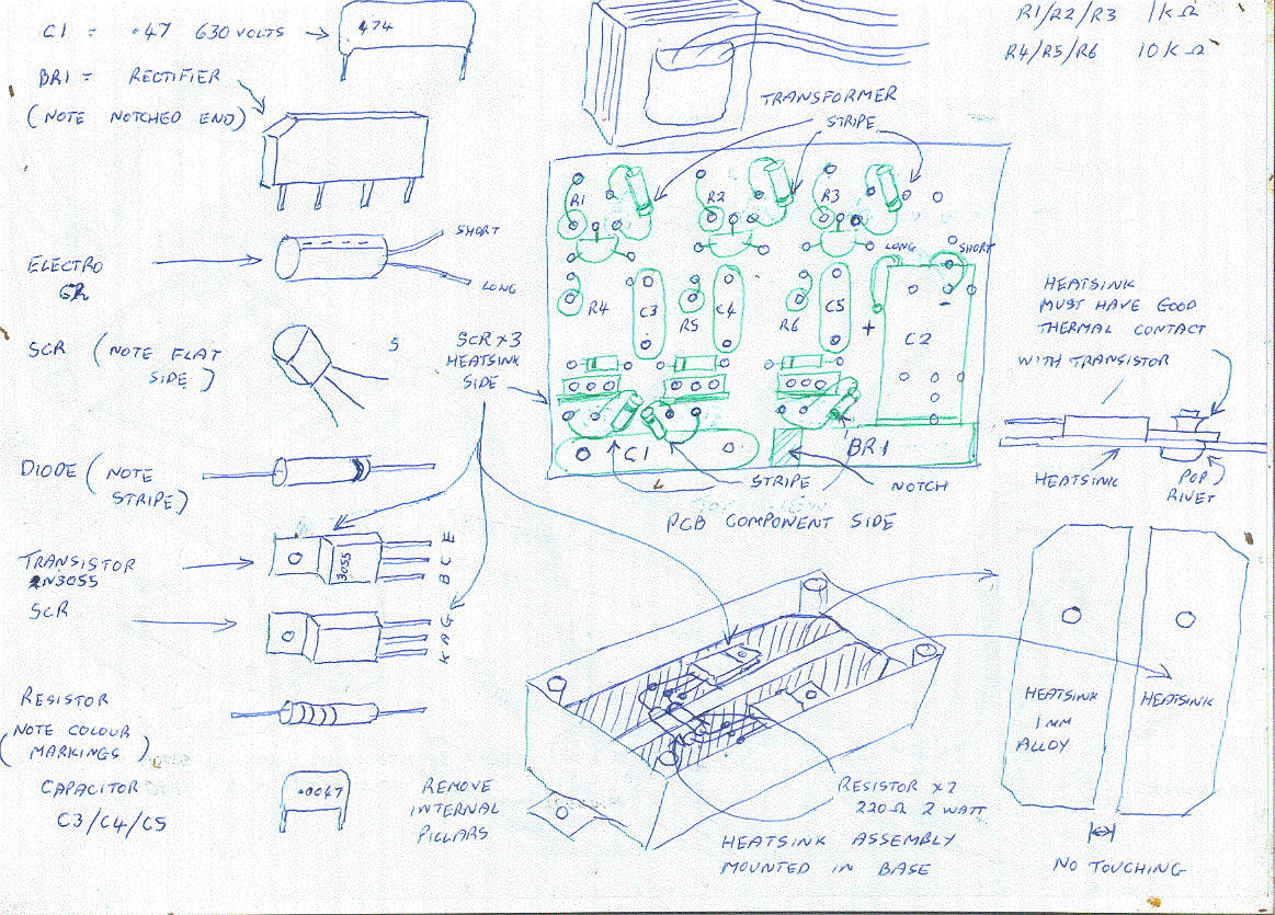

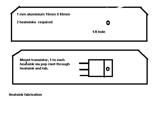
Transistor heatsink and base assembly.
1) remove the 4 small pillars in the base section by snipping off with side cutters
2) Drill 4 small holes 2mm on each side, this will allow the solvents to evaporate
3) Prepare two small aluminum heatsinks from 1mm stock, shape these as per diagram to fit into base. NOTE. It is vital that these do NOT TOUCH when fitted into the base, they are live and must be separated. Drill a 1/8 hole and deburr before pop riveting the two transistors, one to each sink. The surfaces MUST be flat for a goo thermal contact
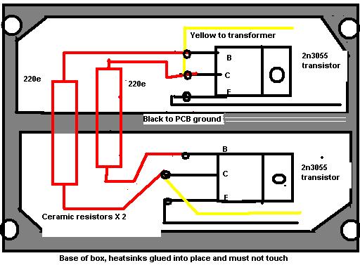
4) With some contact adhesive, fix the heatsinks side by side into the base.
5) Carefully splay the transistor leads and tin each with solder.
6) Form the leads of the two 220 ohm high temp ceramic resitors and solder these to the base and collector leads
7) Solder two 3 inch lengths of insulated wire to the two emitter leads.
8) Carefully adjust each lead to prevent any contact with each other, or the sinks.
9) Dob the connections with adhesive to fix these against vibration.
10) Assembly finished.
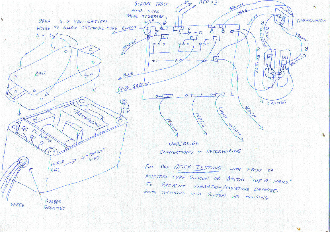
Final assembly, all units
1) Temporarily place the printed circuit board and transformer in the box to gauge the length of wires required from the transformer, and shorten these to suit. Space is tight, so make them as short as possible.
2) With PC board and transformer removed, solder the two yellow transformer wires to the two collector center leads in the base assembly.
3) Solder the white transformer wire to the correct place on the PCB
4) Solder the brown and blue high voltage leads to the two center terminals of the bridge rectifier.
5) solder the two emitter wires to the ground point on the PCB
6) Prepare the coloured wires that will connect to the wiring harness, by stripping the ends and connecting these to the PCB as in the diagram. By using the correct colours, this will validate the testing and fitting procedures.
7) Carefully thread the wires through the housing, after drilling the end housing to take a suitable rubber grommet, and press the board firmly against the end. DO NOT press on the components, this could tear the copper lands from the PCB.
8) Slide the transformer down behind the PCB, taking care that the components are not stressed or bent into contact. Check especially the tabs on the SCRs... these MUST NOT TOUCH. Take care, space is tight.
9) Carefully fit the base to the top section with two screws only... do not overtighten.
10) The unit can now be tested. Go to testing section.
11) Remove the two screws and lift the base. Squirt the filling compound into the case, and base. This will prevent vibration damage and moisture. Immediately refit the base, tighten the four screws and retest the unit. This is your last chance to make good any problems. If all OK, place the unit in a warm place for several days for the filler to harden.
TESTING your unit.
ZX2/1
1) Connect a known good ignition coil to the ORANGE wire from the CDI, ignition primary +
2) Connect a wire from the coil primary - to the BLACK from the CDI
3) Connect the BLACK and coil primary - to the NEGATIVE of a 12 volt battery or power supply
4)Connect the BROWN CDI wire to battery or power supply POSITIVE.
5) Listen carefully for a low pitched hum. If there is a squeel, there is an error, this must be investigated before going any further.
6) Remove power, and remove the base from the unit to allow access to the heatsinks. Attach a spark plug to the HT lead of the coil, and take a wire from the spark plug thread body to battery NEGATIVE, Keeping fingers out, reapply power and touch the YELLOW CDI lead to one heatsink. A shower of sparks should be seen at the plug.
Testing complete.
ZX2/3
The ZX2/3 has three independent channels, these are checked seperately. Channel 1 is yellow/orange, channel 2 is purple/blue, and channel 3 is light green/dark green. Any channel can be abitarily assigned to any cylinder. The circuit is designed to use only one discharge capacitor, to allow the unit to be compact enough to fit the KH400, and uses steering diodes to fire each cylinder in sequence.
Testing is done as follows.
separate each channel into groups, ie light/dark greens, purple/blue, and orange yellow.
1) attach a spark plug into a known good ignition coil, and attach a wire from the threaded plug housing to the BLACK from the CDI
2) Connect these two wires to the NEGATIVE of a 12 volt battery or power supply.
3) Connect the ORANGE CDI wire to the + primary of the ignition coil
4) Connect the - of the ignition coil to one CDI RED
5) Remove the base of the CDI to allow access to the heatsinks
6) Apply power to the CDI. There should be a soft humming, a squeel indicates there is an error and will need remedial work before going further.
7) Touch the YELLOW wire to one heatsink. A shower of sparks should be seen at the plug.
8) Switch off power. Touch one CDI RED to ground.
9) repeat 3) using the dark green, repeat 6)
10) repeat 7) using the light green
11) repeat 3) using the blue, repeat 6)
12) Repeat 7) using the purple.
Testing complete.
Warning Will Robinson
These units generate 550 volts DC, and will remain charged for hours after testing. The ZX2/3 unit is the worst offender at trying to kill the owner. After each test, and with the power OFF, short the RED to ground before going further. This will create a hefty bang as the capacitor discharges, but better safe than sorry. DO NOT touch any other wires other than the YELLOW, LIGHT GREEN or PURPLE when unit is powered up. The ZX2/1 unit is fairly safe, but keep fingers out when powered also.