How to Build
CDI and Magneto Coil Tester
by Starfire
The tester can be constructed in a plastic or wooden box. It tests any CDI
under actual working conditions, and will dynamically test the high voltage
magneto coils, giving a visual indication of their condition...good or bad. It
requires few parts and is very easily assembled. The
tester has been used on the H2, KH400, H1 late and H1 early CDI units. In the
case of the early H1's, this tester will replace the "B" box and test the "A"
box thoroughly.
Click here for diagram
Click here for diagram 2
How it works:
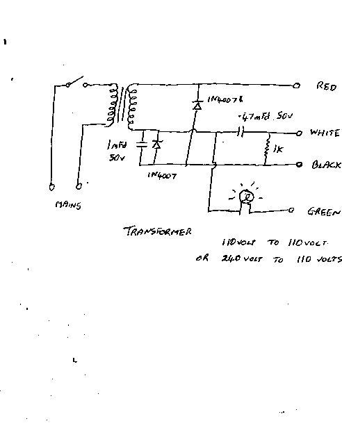
The mains, for safety is fed into a small mains transformer to provide
isolation. For the low powered 110 volt nations, 110 volt to 110 volt
transformer is used. A smallish 1/2 to 1 amp transformer is fine. The high powered
nations with their full allocation of volts will require a 240 to 110 volt job.
The High voltage AC output is fed into the rectifier box on the bike, as with
the H2, or direct into the CDI as in the case of the KH400/H1E etc. A second
output is made to the AC side of the rectifier to further test Magneto coils in
situ, the small incandescent light bulb as used in a fridge or similar is used
as an indicator.
A third AC voltage 180 degrees out of phase with the High voltage output is used
to trigger the CDI at the mains frequency of 50/60 cycles. On a triple, this is
the equivalent of 1 cylinder firing at 3600 rpms or so. it his is handy to have
the CDI left running while being externally heated or cooled to diagnose a
suspected heat related fault.
How to use:
To test a CDI, the CDI Magneto coil inputs and trigger inputs should be
disconnected from the harness. In the case of the H2 for example, this will be
the Green and white from the mag coils, and the three whites from the magneto.
All other wires should be left in place. Switch on the ignition. The RED (high
voltage ) wire from the tester should be connected to the WHITE from the CDI
rectifier box. The BLACK wire from the tester should be securely connected to
the engine. The chosen trigger wire (one of the three whites from the CDI) can
be connected to the WHITE from the tester, each one in turn, to trigger each
cylinder. The WHITE wire from the tester is safe to touch as it is a small 2.8
volt peak to peak signal..... just sufficient to trigger the CDI. Before
testing, remove the sparkplugs from the engine to prevent spontaneous starting,
lay these carefully on the cylinder heads so the spark gaps are visible. DO NOT
run these tests without plugs!!!!
With the tester switched on, the chosen plug should fire without missing, giving
an even buzz. This also tests any suspect ignition coil.
If the trigger coils are suspect, reconnect the three trigger wires only back to
the harness, and kick the bike. With the tester on, the plugs should spark in
sequence. This tests the trigger /signal/pickup coils.
A second way to test the Low speed coil in situ, or a unknown spare, again using
the H2 as an example, the tester should be connected as follows:
The tester GREEN is connected securely to the engine, or the stator casing if
testing a spare off the engine, or the BROWN in the harness if testing off the
bike. The tester RED is connected to the WHITE in the harness, this is the Low
speed coil. Disconnect the harness WHITE from the rectifier box first if on bike
testing. With the tester switched on, the light bulb will tell the condition of
the Low speed coil. If very bright, the Low speed coil has shorted turns, or a
short circuit in the harness. If the bulb remains dark, the Low speed coil has
an open winding or a bad joint in the harness. If the bulb glows dimly, the Low
speed coil is ok.
Always SWITCH OFF the tester before connecting/disconnecting wires. DO NOT
fiddle with any wires with the tester switched on. When used with care, this
tester can save much time and is safe to use.