Points Interface Unit
The ZX unit, fitted to this model bike gives the
following advantages:
1) Easy fitting with the very small size , will convert the S series to either
points driven CDI or with simple mechanical modifications, to the better KH400
system using pick up coils.
2) Retained points last almost indefinitely with timing adjustments remaining
fixed for longer
3) Electrical load on battery/charging circuit reduced dramatically, allowing
brighter and modern lighting to be fitted... approx 48 watts with the old system
to 12 watts with the new.
4) Brings the complete ignition system up to modern standards, and a performance
advantage to match
Using the Starfire universal CDI with a POINTS SYSTEM.
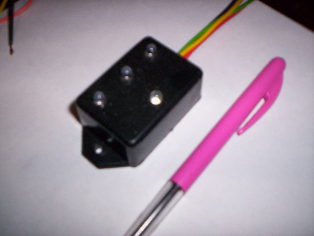
A small additional box is provided to interface the points to the CDI. This will
incorporate the necessary circuitry plus the three LED timing lights. This makes
the initial setup of the engine very easy.
Points Interface Unit
For road racing and drag racing applications.
1) The new CDI will run as a simple minimal equipment, stand alone system.
2) Is compatible with external RPM limiting Tachometers
3) Will run 1.5 hours on a small set of AA nicads or similar... total loss
system for weight reduction.
4) Small and light weight.
5) Potentially allows the rotor, and ALL rotating mass to be completely or
partially removed from the crankshaft.
6) Increased CDI limit of 19000 RPMs!!!!.. a questionable bonus.
7) can use points or pick up/ pulse coils in this configuration.
A relatively simple further upgrade is planned to convert the standard ignition
setup into a full KH400 type system, This will require a replacement stator
plate, and 3 pick up/pulse coils. The original ignition coils can be retained so
can the CDI... it is "future proofed" for this upgrade.
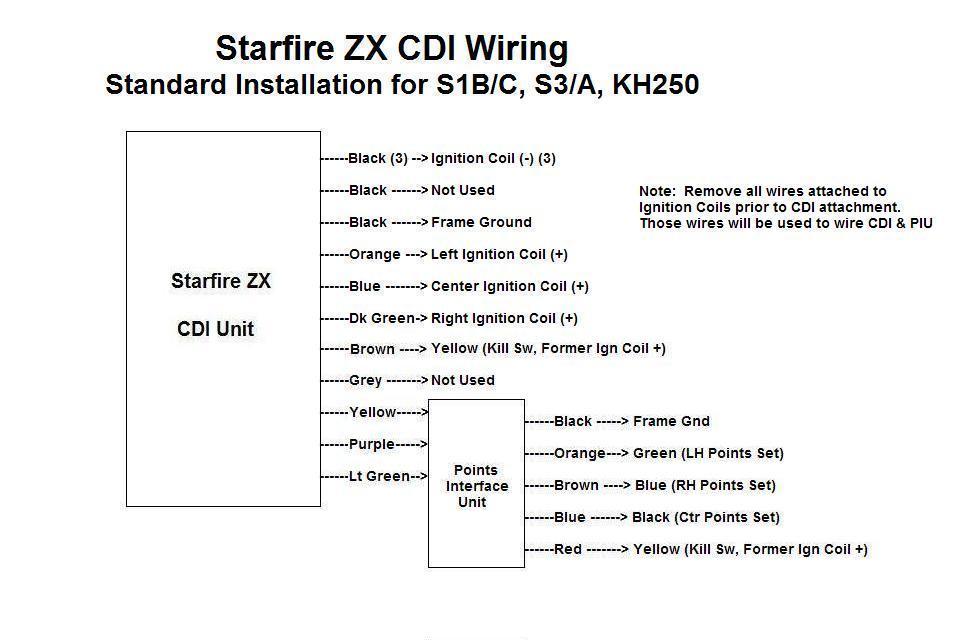
------------STARFIRE ZX CDI INSTALLATION INSTRUCTIONS FOR S1B/C, S3/A, KH250------------
This installation requires the additional
Points Interface Unit with the
RED, ORANGE and GREEN timing lights.
1) Mount CDI unit to bike
2) Remove the YELLOW wires from the coil (+) terminals,
and route these back toward the CDI unit.
3) Remove the GREEN, BLUE, and BLACK wires from the other coil (-) terminals,
and route these back toward the CDI unit.
4) Connect the CDI ORANGE, BLUE and DARK GREEN wires to ignition
coil (+). These are coil left, center and right, respectively.
5) Connect CDI BLACK wires (3) to each
ignition coil (-) terminal.
6) Connect the BROWN CDI wire to the YELLOW connector from step 2
7) Connect one CDI BLACK wire to a firm ground.
8) Mount the Points Interface Unit (PIU) in an accessible place where the
timing lights can be easily seen when setting up the timing.
9) Connect the PIU RED wire to the YELLOW from step 2, also.
10) Connect the CDI YELLOW, PURPLE and LIGHT GREEN wires to the PIU
YELLOW, PURPLE and LIGHT GREEN.
11) Connect the PIU BLACK wire to a firm ground, as in step 7
12) Connect the PIU ORANGE, BROWN and BLUE to the GREEN, BLUE and BLACK
wires removed in step 3
Cut short the remaining unused CDI wires protecting the ends with a dab
of nail varnish.
These are BLACK x 1, GREY x 1
The bike will now run with the new CDI. The three "traffic light" LED's
will make setting of timing a breeze.
The GREY wire may be taken to a kill switch, or perhaps a hidden switch
as an anti theft deterrent. This wire is grounded to stop the engine, or
to prevent it starting.
A future upgrade is planned to convert this model to magnetic
triggering. A modified stator plate and magnetic trigger will be
included for easy installation. The CDI will remain unchanged, The
Points Interface Unit will be discarded.
CLICK HERE FOR PICTORIAL WIRING DIAGRAM
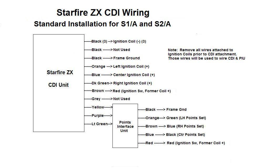
---------STARFIRE
ZX CDI INSTALLATION INSTRUCTIONS FOR
S1/A, S2/A---------
This installation requires the additional Points Interface Unit with the
RED, ORANGE and GREEN timing lights.
1) Mount CDI unit to bike
2) Remove the RED wires from the coil (+) terminals,
and route these back toward the CDI unit.
3) Remove the GREEN, BLUE, and BLACK wires from the other coil (-) terminals,
and route these back toward the CDI unit.
4) Connect the CDI ORANGE, BLUE and DARK GREEN wires to ignition
coil (+). These are coil left, center and right, respectively.
5) Connect CDI BLACK wires (3) to each
ignition coil (-) terminal.
6) Connect the BROWN CDI wire to the RED double connector from step 2
7) Connect one CDI BLACK wire to a firm ground.
8) Mount the Points Interface Unit (PIU) in a accessible place where the
timing lights can be easily seen when setting up the timing.
9) Connect the RED wire from the PIU also to the RED from step 2
10) Connect the CDI YELLOW, PURPLE and LIGHT GREEN wires to the PIU
YELLOW, PURPLE and LIGHT GREEN.
11) Connect the PIU BLACK wire to a firm ground, as in step 7
12) Connect the PIU ORANGE, BROWN and BLUE to the GREEN, BLUE and BLACK
wires removed in step 3
Cut short the remaining unused CDI wires protecting the ends with a dab
of nail varnish.
These are BLACK x 1, GREY x 1
The bike will now run with the new CDI. The three "traffic light) leds
will make setting of timing a breeze.
The GREY wire may be taken to a kill switch, or perhaps a hidden switch
as an anti theft deterrent. This wire is grounded to stop the engine, or
to prevent it starting.
A future upgrade is planned to convert this model to magnetic
triggering. A modified stator plate and magnetic trigger will be
included for easy installation. The CDI will remain unchanged, The
Points Interface Unit will be discarded.
CLICK
HERE FOR PICTORIAL WIRING DIAGRAM
---------STARFIRE
ZX CDI INSTALLATION INSTRUCTIONS FOR
H1B---------
This installation requires the additional Points Interface Unit with the
RED, ORANGE and GREEN timing lights.
1) Mount CDI unit to bike
2) Remove the BROWN wires from the coil (+) terminals,
and route these back toward the CDI unit.
3) Remove the GREEN, RED/WHITE, and BLACK wires from the other coil (-)
terminals,
and route these back toward the CDI unit.
4) Connect the CDI ORANGE, BLUE and DARK GREEN wires to ignition
coil (+). These are coil left, center and right, respectively.
5) Connect CDI BLACK wires (3) to each
ignition coil (-) terminal.
6) Connect the BROWN CDI wire to a BROWN connector from step 2
7) Connect one CDI BLACK wire to a firm ground.
8) Mount the Points Interface Unit (PIU) in a accessible place where the
timing lights can be easily seen when setting up the timing.
9) Connect the RED wire from the PIU also to the RED from step 2
10) Connect the CDI YELLOW, PURPLE and LIGHT GREEN wires to the PIU
YELLOW, PURPLE and LIGHT GREEN.
11) Connect the PIU BLACK wire to a firm ground, as in step 7
12) Connect the PIU ORANGE, BROWN and BLUE to the GREEN, RED/WHITE,
and BLACK wires removed in step 3
Cut short the remaining unused CDI wires protecting the ends with a dab
of nail varnish.
These are BLACK x 1, GREY x 1
The bike will now run with the new CDI. The three "traffic light) leds
will make setting of timing a breeze.
The GREY wire may be taken to a kill switch, or perhaps a hidden switch
as an anti theft deterrent. This wire is grounded to stop the engine, or
to prevent it starting.
A future upgrade is planned to convert this model to magnetic
triggering. A modified stator plate and magnetic trigger will be
included for easy installation. The CDI will remain unchanged, The
Points Interface Unit will be discarded.
CLICK
HERE FOR PICTORIAL WIRING DIAGRAM